PV String Design Explained: Series, Parallel & MPPT Matching
Introduction
A solar system’s capacity — whether 3 kW, 5 kW, or 50 kW — doesn’t tell the full story. The real performance comes from how you connect your panels and how well their output matches the MPPT input range of your inverter or charge controller.
I often compare this process to a word scramble. You may have all the right letters (solar panels), but until you arrange them in the correct order (series and parallel), they don’t form a meaningful word — your PV string.
In this post, we’ll learn how to size and connect solar panels step-by-step, arranging them in the right series–parallel combination and ensuring they operate safely and efficiently within the inverter’s MPPT window — the heart of every well-designed solar system.
How does a Grid-tied solar power system work?
Before diving into PV string design, let’s quickly understand how a grid-tied solar power system works as a whole. This will help you visualize where the “string” actually fits in.
When sunlight falls on solar panels, each panel produces direct current (DC) electricity.
Now, when multiple panels are connected correctly in series and parallel, their combined voltage and current perfectly match the input window of the inverter. The inverter’s job is to convert this DC power into alternating current (AC) that can run your home appliances or export to the grid.
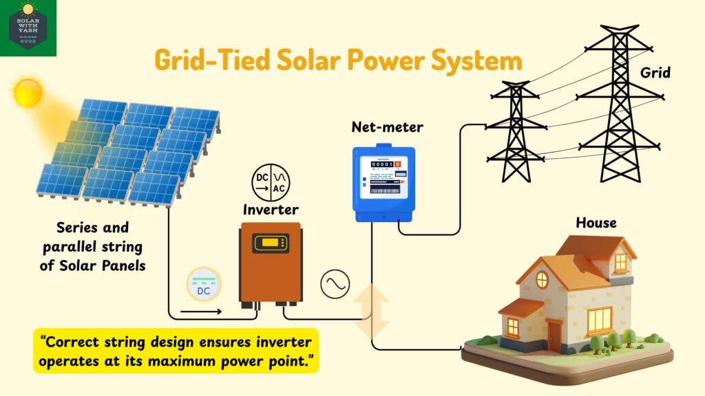
If the panels are not connected properly — say, the total voltage is below the inverter’s minimum MPPT range or above its maximum limit — the inverter will not perform efficiently or may even fail to start.
In simple words: When your solar panels are arranged correctly, their combined output aligns with the inverter’s MPPT input — and that’s when your system starts delivering clean, usable electricity.
Key Takeaways:
- PV string design ensures your panel voltage and current match the inverter input.
- Inverter MPPT keeps the system operating at maximum power point automatically.
- A well-designed string = efficient conversion and maximum energy harvest.
Example: A Simple 5kW Grid-Tied Solar Power System
To understand how solar panels are connected, let’s take a small real-world example.
Imagine I have a 5kW grid-tied solar power system. It’s connected to a 5kVA solar inverter, whose job is to convert the DC electricity from solar panels into AC electricity that can run my home appliances or export power to the grid.
Now, every inverter has an input voltage range — this is the window within which it can operate efficiently.
For my 5 kVA inverter, this MPPT input voltage range is 120 volts to 600 volts.
On the other hand, I have 10 solar panels of 500 watts each, with the following specifications:
- Vmp (Voltage at Maximum Power): 45 V
- Imp (Current at Maximum Power): 11.11 A
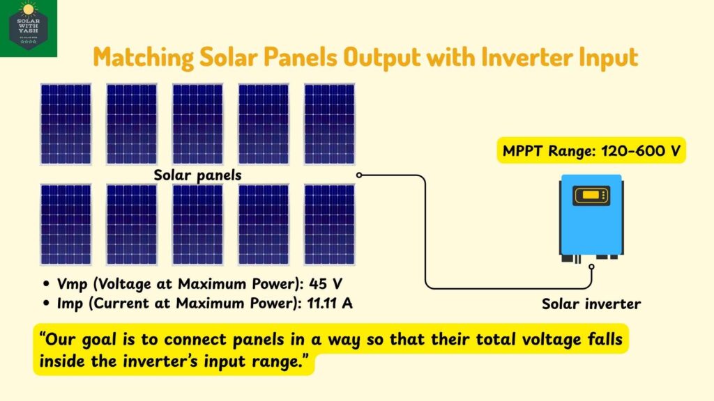
So, if each panel delivers 45 volts at maximum power, I need to connect them in such a way — series, parallel, or a mix of both — that the resultant voltage stays within my inverter’s 120–600 V input window.
In simple words:
Our goal is to “arrange” the panels correctly so the total voltage and current perfectly match what the inverter expects.
Once this concept is clear, understanding series and parallel connections becomes much easier — because they are the building blocks of every PV string design.
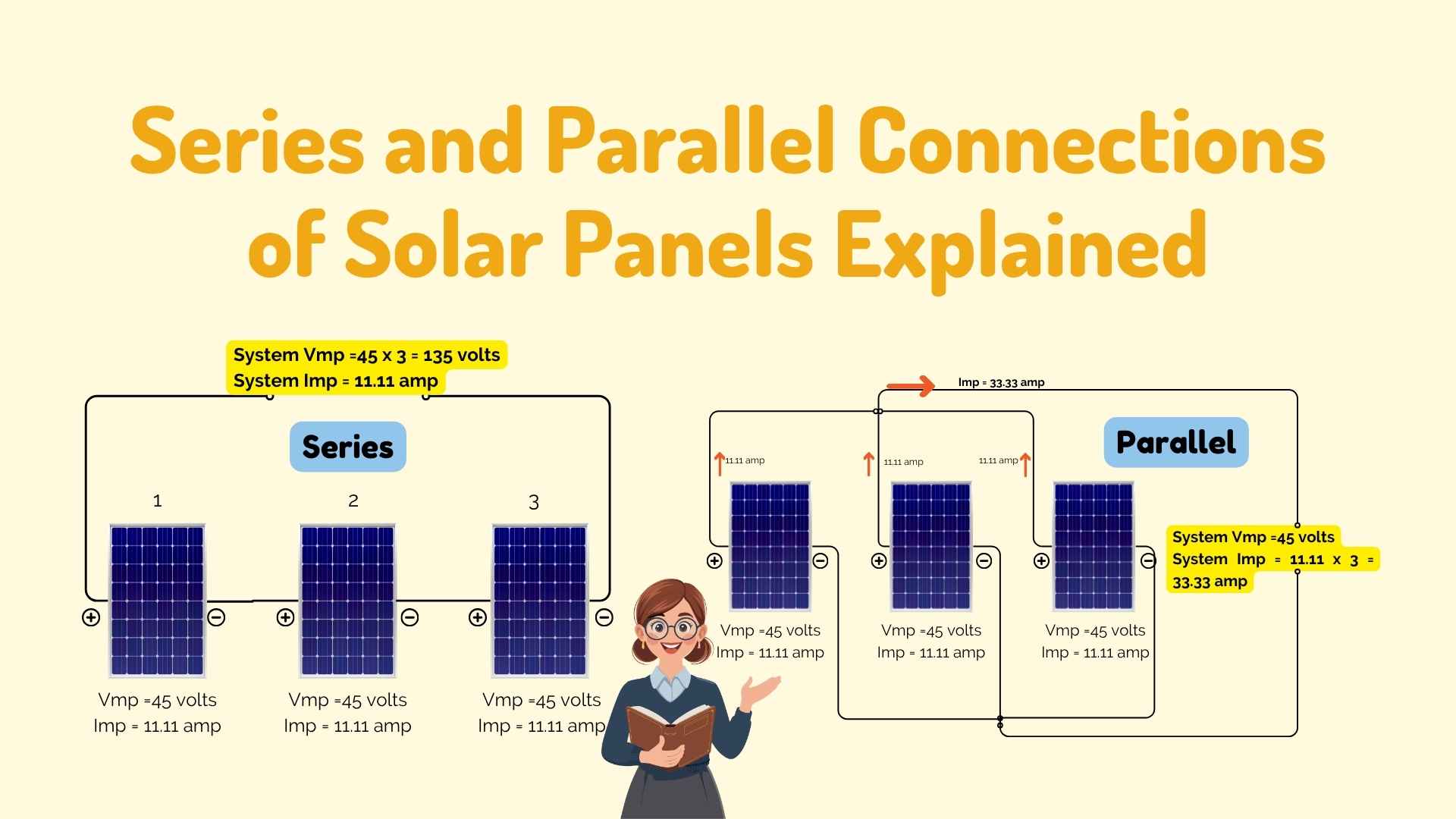
Series Connection of Solar Panels
In a series connection, the positive terminal of one solar panel is connected to the negative terminal of the next — much like joining them head to tail in a chain. This arrangement increases the overall voltage of the solar array while the current remains the same as that of a single panel.
You can imagine this like connecting batteries in series — their voltages add up, giving a higher total voltage output, but the current doesn’t change.
Let’s take an example to understand this better.
Suppose we have three solar panels, each rated at Vmp = 45 volts and Imp = 11.11 amperes.
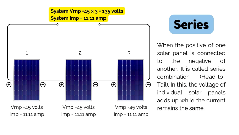
If we connect these panels in series:
- The total voltage will be the sum of all panel voltages:
45 V + 45 V + 45 V = 135 V - The total current will remain the same as that of one panel:
Imp = 11.11 A
So, the combined output of this 3-panel series string is:
Vmp (total) = 135 volts, Imp (total) = 11.11 amperes
In short:
Series connection = Voltage adds up, Current stays constant.
This simple principle forms the basis of every solar string design. By connecting panels in series, we can increase the total DC voltage to fall within the inverter’s MPPT operating window — ensuring it works efficiently even under varying sunlight conditions.
Parallel Connection of Solar Panels
In a parallel connection, the positive terminals of all solar panels are connected together, and the negative terminals are also connected together. This setup increases the total current output, while the voltage remains the same as that of a single panel.
You can think of it like adding extra lanes to a highway — more cars (current) can flow through at the same speed (voltage). Let’s take the same example of three solar panels, each rated at Vmp = 45 volts and Imp = 11.11 amperes.
If these panels are connected in parallel:
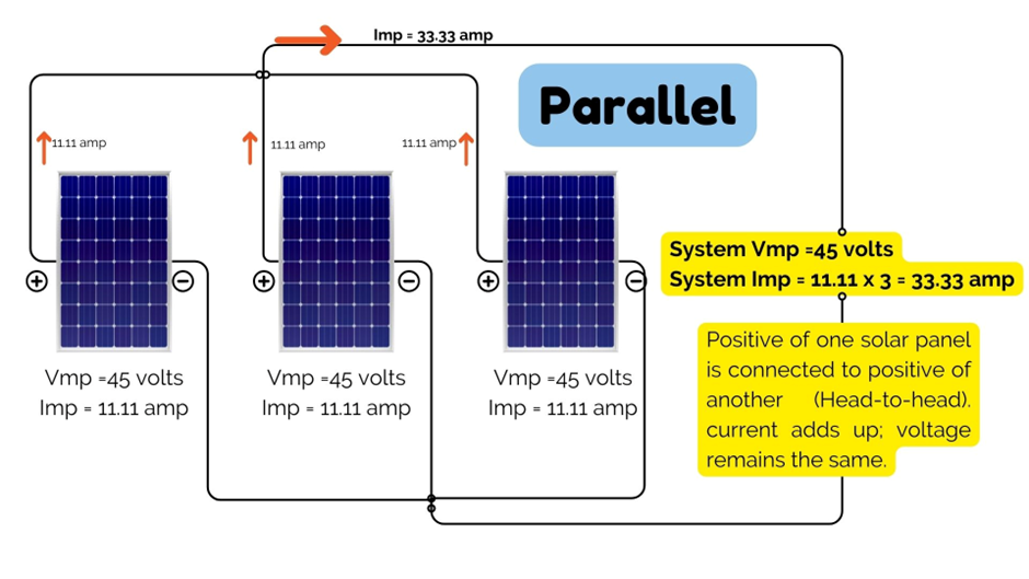
The voltage of the system remains the same as a single panel:
Vmp (total) = 45 volts
- The current adds up from each panel:
- Imp (total) = 11.11 + 11.11 + 11.11 = 33.33 amperes
So, the combined output of this 3-panel parallel system is:
Vmp (total) = 45 volts, Imp (total) = 33.33 amperes
In simple words:
Parallel connection = Current adds up, Voltage stays constant.
This type of connection is useful when you want to increase the system’s total current to match the inverter’s input current capacity — or when designing low-voltage, high-current systems such as for off-grid setups.
Combining Series and Parallel Connections for PV String Design
Now, let’s come back to our main example and put everything together.
We have 10 solar panels; each rated at 500 W with:
- Vmp = 45 V (voltage at maximum power)
- Imp = 11.11 A (current at maximum power)
The inverter we’re using is a 5 kVA grid-tied solar inverter with an input MPPT voltage range of 120 V to 600 V.
Our task is to connect these panels — in series, parallel, or a mix of both — so that the final voltage and current stay within this operating window.
Formula Refresher: The power output of each panel can be written as:
P(max) = Vmp x Imp
For a 500 W panel: 45volts x11.11ampere
Case 1: One Series String (All 10 Panels in Series)
In this configuration, the positive terminal of one panel connects to the negative of the next, forming a single chain of 10 panels.
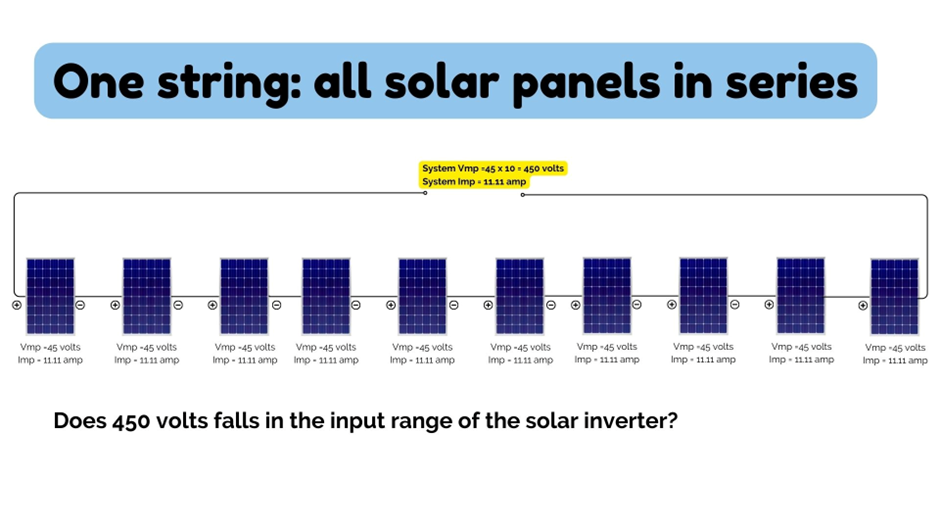
Calculation
- Total Voltage = 45 V × 10 = 450 V
- Total Current = 11.11 A (same as one panel)
Result:
- System Output = 450 V, 11.11 A
Since 450 V lies comfortably within the inverter’s input range (120–600 V), the inverter will operate efficiently and convert this DC power into AC for household use or grid export.
Case 2: Two Strings of Panels (Series + Parallel Combination)
Let’s try another configuration — a 2-string system.
Here, we’ll connect 5 panels in series to form one string and another 5 panels in series for the second string.
Then we’ll connect both strings in parallel.
String 1:
- Voltage = 45 V × 5 = 225 V
- Current = 11.11 A
String 2:
- Voltage = 225 V (same as String 1)
- Current = 11.11 A
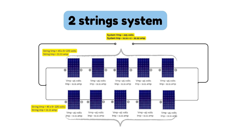
System Output
- Voltage = 225 V
- Current = 11.11 A + 11.11 A = 22.22 A
Since 225 V also falls within the inverter’s MPPT range (120–600 V), the inverter will easily accept this input and convert it into usable AC electricity.
What This Means
This simple hit-and-trial approach shows how different series-parallel combinations affect your system’s voltage and current — and how only the right arrangement ensures your PV string design matches the solar inverter input voltage range.
In real-world design, engineers use this understanding to:
- Optimize the number of panels per string for efficiency and safety
- Keep voltage within inverter and temperature limits
- Balance current flow for maximum MPPT performance
In short:
The heart of PV string design is arranging panels so that their combined DC output perfectly fits the inverter’s MPPT input window.
Understanding MPPT Matching and Temperature Impact on Voltage
So far, we’ve seen how the right series–parallel combination helps us get the required voltage and current to match our inverter’s input range. But there’s one more factor that can completely change your design: temperature.
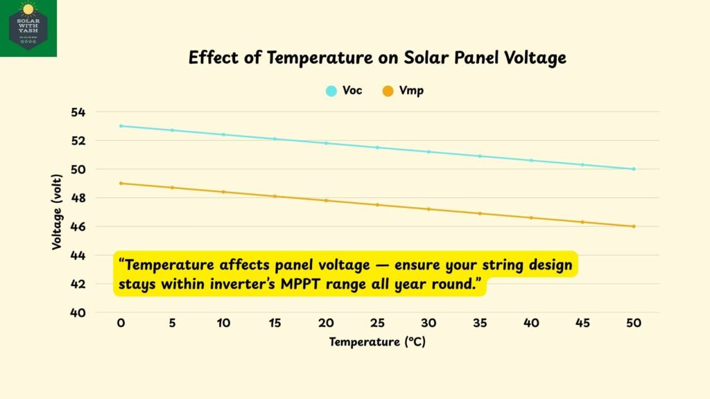
The output voltage of a solar panel doesn’t stay fixed — it rises in winter and drops in summer. That means the same PV string can produce different voltages throughout the year.
This is where MPPT matching becomes crucial.
What is MPPT Matching?
Every inverter has a range called the MPPT voltage window — it’s the DC voltage range within which the inverter can efficiently extract maximum power from your solar panels.
If your string voltage:
- Falls below the minimum MPPT voltage → the inverter will not start.
- Exceeds the maximum voltage → the inverter can shut down or get damaged.
So, during design, you must ensure that your string voltage stays within the MPPT range — even when temperatures vary.
Example: Temperature Effect in North India
Let’s take the same 5 kW system example for a location in North India, where:
- Summer temperature: around 45°C
- Winter temperature: around 5°C
Each Solar Panel has:
- Voc (Open Circuit Voltage): 50 V
- Temperature coefficient of Voc: –0.3%/°C
Step 1: Find the Voc at the Lowest Temperature (Winter)
When the temperature drops, voltage increases.
We calculate corrected voltage using:

Substitute the values:

So, at 5°C, each panel gives around 53 volts.
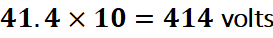
If 10 panels are in series →
✅ Still within inverter’s maximum limit (600 V), so it’s safe.
🔹 Step 2: Find the Vmp at the Highest Temperature (Summer)
When temperature rises, voltage drops.
Let’s assume Vmp temperature coefficient = –0.4%/°C

For 10 panels in series:
✅ Still above the inverter’s minimum MPPT voltage (120 V).So, across North India’s 5°C to 45°C range, this string remains within safe MPPT limits (120–600 V) — perfect design!
Why Temperature Check Is So Important
Even a well-sized system can fail if temperature isn’t considered:
- In cold regions, Voc can rise dangerously high, crossing the inverter’s limit.
- In hot summers, Vmp can fall too low, causing inverter underperformance.
- Proper MPPT matching ensures your inverter always operates efficiently — even under extreme conditions.
In short:
- Cold weather = Higher voltage (risk of overvoltage)
- Hot weather = Lower voltage (risk of under-voltage)
- Perfect string design = Always within MPPT range
Common Mistakes in PV String Design (and How to Avoid Them)
Even with the right number of panels and a good inverter, small mistakes in PV string design can drastically reduce your system’s performance — or even cause inverter faults.
Let’s look at some of the most common ones and how to prevent them.
Ignoring Temperature Effects
Many installers design strings using standard test condition (STC) voltages without considering seasonal temperature variations.
As we discussed earlier, in regions like North India, the voltage can rise sharply in winters (as temperature drops) and fall in hot summers.
✅ How to Avoid:
Always apply temperature correction using panel datasheet coefficients and check that:
- Maximum Voc (at lowest temp) < inverter’s max DC input
- Minimum Vmp (at highest temp) > inverter’s min MPPT voltage
This ensures your system remains within the inverter’s safe operating window all year round.
Unequal String Lengths or Mismatched Panels
Sometimes, installers mix panels of different capacities or create uneven strings (like one string with 10 panels and another with 8).
This leads to mismatch losses, uneven current flow, and reduced generation.
✅ How to Avoid:
Keep all strings identical in voltage and current rating — use the same number of panels, same make and model, and similar cable lengths.
Exceeding Inverter Voltage Limit
Overvoltage is a silent killer.
If your total string Voc exceeds the inverter’s rated limit (say 600 V or 1000 V depending on model), it can permanently damage the inverter input circuitry.
✅ How to Avoid:
Use the Voc @ lowest temperature formula during design.
Always keep a 10% safety margin below the inverter’s maximum DC voltage.
Operating Below MPPT Voltage Range
If the total Vmp of your string falls below the inverter’s minimum MPPT voltage, your inverter will not track maximum power efficiently — leading to poor performance and lower energy yield.
✅ How to Avoid:
Make sure your string Vmp (at hottest temperature) is always higher than inverter’s minimum MPPT voltage (e.g., >120 V).
Check inverter datasheet carefully.
Poor Cable Sizing
Even if your string design is perfect, long DC cable runs or undersized wires cause voltage drop losses — effectively wasting part of your generation.
✅ How to Avoid:
- Use DC cables of proper cross-section (typically 4 mm² or 6 mm² for rooftop systems).
- Keep voltage drop below 2% of total system voltage.
- Use cable sizing formulas or tools (like the one in your upcoming mini-course).
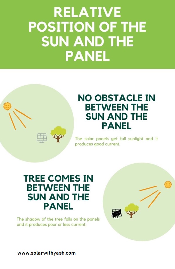
Ignoring Shading and Orientation
Shading on even one panel in a series string can reduce the current of the entire string.
This is one of the most overlooked causes of poor generation in residential systems.
✅ How to Avoid:
- Keep all panels in a string facing the same direction and tilt.
- Avoid placing panels under shadows from trees, walls, or tanks.
- Consider separate MPPT trackers for arrays facing different directions (e.g., East–West rooftops).
No Safety Margin or Oversizing
Some designers try to squeeze as many panels as possible to hit the upper inverter voltage limit.
This leaves no safety margin for temperature fluctuations or voltage spikes.
✅ How to Avoid:
Always leave 5–10% headroom below the inverter’s max input voltage and current ratings.
Design for reliability, not just for maximum numbers.
💡 Quick Recap
| Mistake | What Happens | How to Fix |
|---|---|---|
| Ignoring temperature | Inverter shutdown or damage | Apply temp correction |
| Unequal strings | Mismatch losses | Keep strings identical |
| Overvoltage | Inverter failure | Keep Voc < max DC voltage |
| Undervoltage | Poor efficiency | Vmp > min MPPT |
| Thin cables | Power loss | Size for <2% drop |
| Shading | Low generation | Avoid or separate MPPTs |
| No margin | Unstable system | Keep 5–10% safety headroom |
Final Word: Design Smart, Not Just Fast
String design isn’t about connecting panels randomly until the voltage “fits.”
It’s about understanding how voltage, current, and temperature interact — and ensuring your system performs safely and efficiently year-round.
- The right arrangement of the solar panels is important so that their output voltage falls in the input voltage range of the solar inverter.
- This arrangement could be in series, parallel, or a combination of both.
- In series, the voltage adds up while the current remains the same.
- In parallel, the current adds up and the voltage remains the same.
- P(max) = Vmp x Imp
💡 Ready to design your own solar system?
Use my Solar Feasibility Spreadsheet (SFS) to calculate system size, ROI, and payback — all based on your exact location and electricity bill.
Frequently Asked Questions on PV String Design
- What is PV string design in solar systems?
PV string design means arranging solar panels in series and parallel combinations so their total voltage and current match the inverter’s MPPT input range. It ensures your inverter operates safely and efficiently, converting DC from panels into usable AC power.
2. Why is MPPT matching important in solar design?
MPPT (Maximum Power Point Tracking) ensures the inverter extracts maximum power from the panels. If your string voltage falls outside the inverter’s MPPT range — too high or too low — the inverter will either shut down or work inefficiently. Correct string design keeps it within this window.
3. How does temperature affect solar panel voltage?
Solar panel voltage increases in cold weather and decreases in hot weather. That’s why, in regions like North India, you must calculate both coldest and hottest temperature voltages to ensure your system stays within the inverter’s safe operating range.
4. What’s the difference between series and parallel connections?
- Series connection: Voltage adds up, current remains the same.
- Parallel connection: Current adds up, voltage remains the same.
Most rooftop systems use a combination of both to match inverter input and achieve the desired power output.
5. How many panels should I connect per string?
The number of panels per string depends on:
- The inverter’s MPPT voltage range
- The panel’s Voc and Vmp values
- The temperature range of your location
- For most 5 kW residential systems, it’s typically between 8 and 12 panels per string, but always calculate using temperature-corrected voltage values.
6. Can wrong string design damage the inverter?
Yes. If the string voltage exceeds the inverter’s maximum DC voltage, it can permanently damage the inverter input circuit. If it’s below the minimum MPPT voltage, the inverter won’t start or will perform poorly. That’s why correct string design is essential.
Bonus Tip:
Always keep a 5–10% safety margin below the inverter’s maximum voltage limit and design strings for your coldest local temperature — that’s where most overvoltage issues occur.